KAP | Making the Camera Tray of the KAP Rig
by Matthew Cole
My rigs are of very conventional design and embody no real advanced design features. However, to someone unfamiliar with KAP rigs or working with aluminum, this page will provide some guidance on what is involved in building a rig. In this case, I go into a bit of detail on making the camera tray (or camera bracket, or tilt bracket) of my G500 rig (that's for the Minolta Dimage G500 digital point'n'shoot camera, not some arcane numbering system of my own).
One of the challenges in KAP rig building is that you may need to bend metal. You can get away without this, using, for instance, a piece of wood for the top deck of the rig and screwing flat metal sides into the ends of it, assembling a U-shaped bracket from three separate pieces and some right-angle stock, or other approaches. Me, I figured that it was just as easy to make the pieces from a single piece of alumnium bent to shape.
On my first from-scratch rig, built for my Contax G1 camera, I bent the metal by clamping it in a vise and whacking it with a hammer to a 90-degree bend. This looked, not to put too fine a point on it, like shit. I've been in Brooks Leffler's garage and he has some nice metal brakes and shears, for bending and cutting his stuff, but I didn't want to spend a pile o' money for a limited-use tool. I read on the web about the Mighty-Mite metal brake, bench-mounted and hand-operated, for about $45, and went out to Northern Tool and Equipment and bought one. Cool!
This tool needs to be mounted somewhere, so I drilled four holes in my basement workbench top and put threaded T-nut inserts underneath. Now, when I need to bend a piece of aluminum, I pull out the Mighty-Mite, bolt it down to the bench, and bend away.
It should be noted that small brakes like this have their limitations. For one thing, the 1/16" thick aluminum that I use for my KAP rig fabrication is at about the upper limit for thickness for this thing. Also, it won't bend a 1/4" lip into a foot-long piece of aluminum, for instance. Still, it does do nice bends in the dimensions I require.
The other thing I illustrate on this page is putting some small right-angle brackets on the camera tray. These are there to keep the camera from pivoting should the tripod screw come a bit loose. You don't want the darn thing unscrewing itself, and the brackets make sure the camera remains properly aligned. I made these out of 3/4" X 1/2" right-angle aluminum stock (from the hardware store). I bought a 72"-long piece and used less than 2 inches of it, so I'm set for my next 30 or so rigs! The reason I went with the 3/4" X 1/2" rather than 1/2" X 1/2" is that I riveted these things to the camera tray using countersunk rivets and the nose of my rivet gun was too big to get into position with a 1/2" riveting surface.
Without further ado, here's some of the steps in building the camera tray.
|
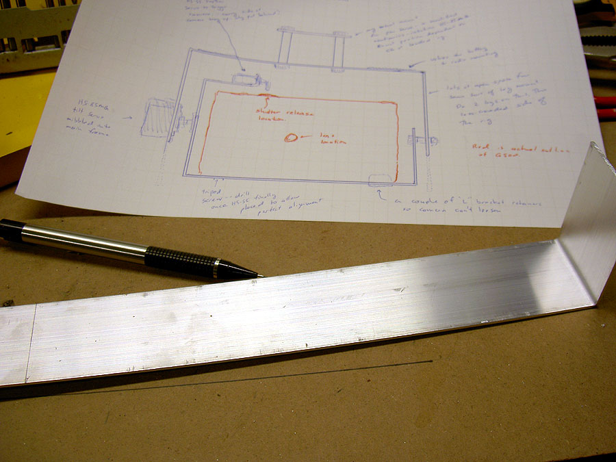
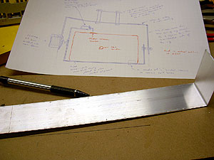
Marking The Aluminum Here I am marking the length of aluminum stock I need for my camera tray. Typically I'd do this on a flat piece but I came home all enthusiastic with my new metal brake and bent that one end. It was so exciting! Anyway, I am working from my roughed-out plans, drawn to size, on the sheet of paper above. If you visit Cris Benton's site, he'll have these lovely blueprint-like drawings, but then he's an architecture prof and I'm a lowly economist. Minolta G500 digital
|
|
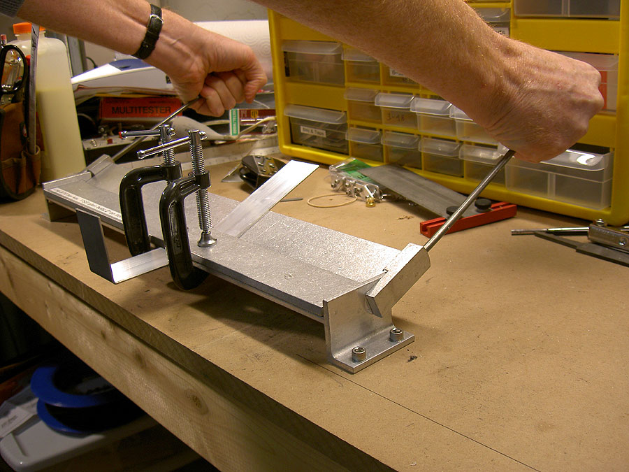
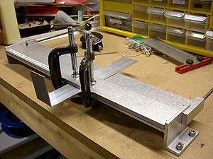
Clamp the workpiece in the brake Here you can see the Mighty Mite brake bolted to my workbench. I have the workpiece clamped in place. There is a long iron bar that goes along the top of the bend and those C-Clamps are holding it and my piece of aluminum, in position. Changing the distance back from the bend to the edge of that bar will change the radius of the bend to some extent. Minolta G500 digital
|

|
Bending the Aluminum in the metal brake Here you can admire the bulging veins on my burly arms as I bend the metal with my bare hands! It is actually pretty easy, using the miracle of leverage. This is partway through the bend. Minolta G500 digital
|
|
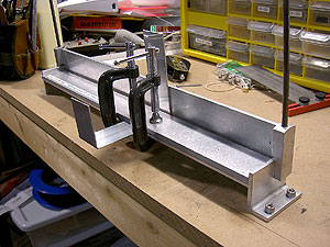
The Bend Completed There, that's done. There is more bending to be done, as the piece just bent is going to come back across the top of the camera to mount the shutter release on. Still, you get the idea. Of course, this isn't strictly necessary, the vise'n'whack system works too and most people aren't going to be inspecting the workmanship of your rig, but it's always fun to buy new tools. Minolta G500 digital
|
|
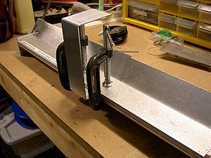
The Final Bend, mostly done Almost forgot I had a photo of this, this is putting the final bend in the camera tray piece, a shelf for the shutter release servo to mount on. Minolta G500 digital
|
The next bit on the camera tray will relate to drilling the tripod screw hole and then mounting the little rotation-prevention brackets, to help hold the camera steady. The shutter release servo and bracket miraculously appear in these photos, having been built separately. Their construction is covered elsewhere in my KAP pages.
|
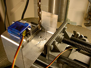
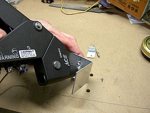
Mark the position for the hole As you get further into the work on a piece, you become more careful because there are more steps which you would have to repeat! Here, I mark the location for the hole for the tripod screw. This is the 1/4-20 short bolt that will screw into the bottom of the camera and holdt to the tray. You can see the precision marking guide in the background. This is a really handy aid. You can also see that this is out-of-sequence, since the shutter release bracket hasn't been mounted yet. Minolta G500 digital
|

|
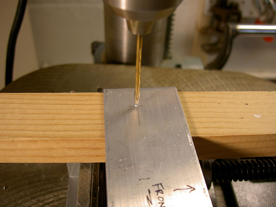
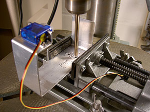
Drilling the Tripod Screw Pilot Hole It bears repeating that, if you want your bigger hole in the right spot, drill a precisely located smaller pilot hole first. Here goes the one for the tripod screw hole. The workpiece is clamped in the drill press vise and the piece of scrap wood is supporting it while it is drilled. Minolta G500 digital
|
|
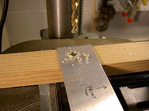
The Final Hole for the Mounting Screw is Drilled The workpiece remains clamped, all the drill press settings are locked, you switch bits and drill the final hole. This will obviously need a bit of tidying up with a file but you get the idea. Minolta G500 digital
|
You can, by the way, see an actual cheesy video of A Piece of Aluminum Getting Drilled. Exciting it's not, but if you have never drilled metal before and are wondering how hard that is, you can see it. Note that I stupidly turned the camera vertically, so it looks as if though I have my drill press mounted horizontally out from the wall with a powerful magnet to attract even normally non-ferrous aluminum scraps. Just tilt your head sideways or turn the monitor 90 degrees, it'll look fine. You can also see a cheesy video of me Sawing A Piece of Aluminum with a Hacksaw. Again, it is boring in the extreme, but if you want to see how fast a bimetal hacksaw blade eats through a piece of 1.5" aluminum, this is the place! Note that while neither of these videos is very exciting, they are at least real big; 3 Meg to see the hole drilled, 4 Meg to see the aluminum sawed off.
|
Drilling Countersunk Rivet Holes I want to mount these little L brackets to keep the camera from rotating, but the camera tray under the camera needs to remain flat. The answer; countersunk rivets! (Actually, epoxy glue might well have worked as well, but I distrust adhesives). In this fine photo, you can see how I have already drilled the small holes for the rivets all the way through and am now using a much larger bit to do the countersink depression. This is yet another time when the drill press is invaluable--clamp the part, lock everything in place and drill your countersink to just the right depth (checked with a rivet). Minolta G500 digital
|
|
Test-Fitting A Countersunk Rivet Here is how I check the countersink shoulder with a rivet--you just put it in place. The drill press makes it easy to take just a hair more material when needed. This would be tough with a hand drill. Minolta G500 digital
|

|
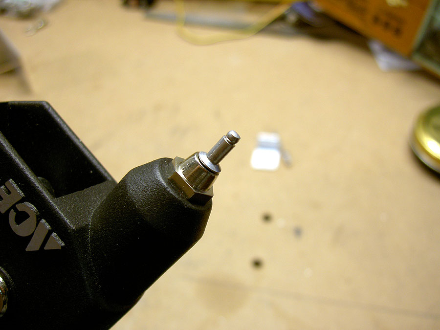
A Countersink Rivet in the Rivet Tool This is what a countersink rivet looks like when mounted in the rivet tool. Minolta G500 digital
|
|
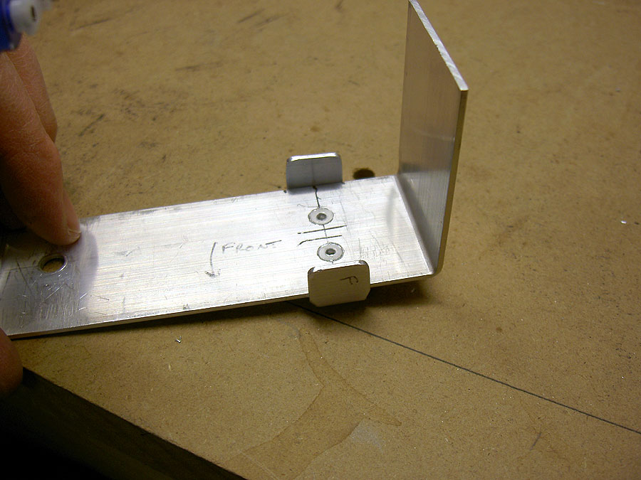
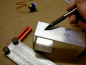
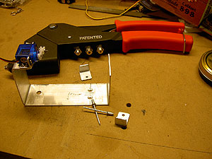
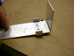
Ready to Rivet the Retaining Brackets Here is everything ready to go; rivet tool, rivets, little retaining brackets marked for front and rear. Minolta G500 digital
|
|
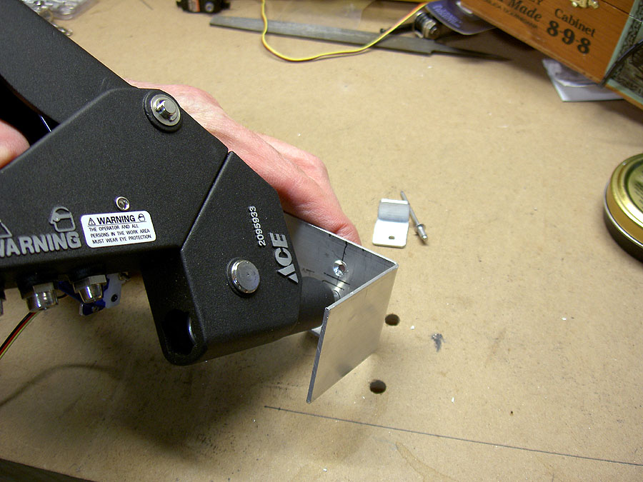
Riveting on a Retaining Bracket Here I rivet on one of the little retaining brackets. I think I mention elsewhere that the size of the nose on this rivet tool required me to use 3/4" X 1/2" aluminum material rather than 1/2" X 1/2". If you've never used a pop rivet tool before, you just stick the rivet in the tool poke the rivet through the holes you've already drilled, and then squeeze the handles. The little nail thing in the middle of the rivet pulls through, squeezing the rivet tight and then snapping off. It is mechanically a sound joint but not the prettiest thing you've ever seen. Minolta G500 digital
|
|
Bracket Riveting Finished There, all done! The countersunk rivets are flush with the bottom of the camera tray so won't disrupt the camera mounting. The faces of the brackets are a bit far apart (I actually could have used 1.25" aluminum for the camera tray rather than 1.5" but couldn't find any that size and distrusted my ability to cleanly rip a 1/4" strip off the tray workpiece) so I applied a bit of adhesive rubber stuff to them. That'll also keep the camera from getting scratched. Minolta G500 digital
|
|
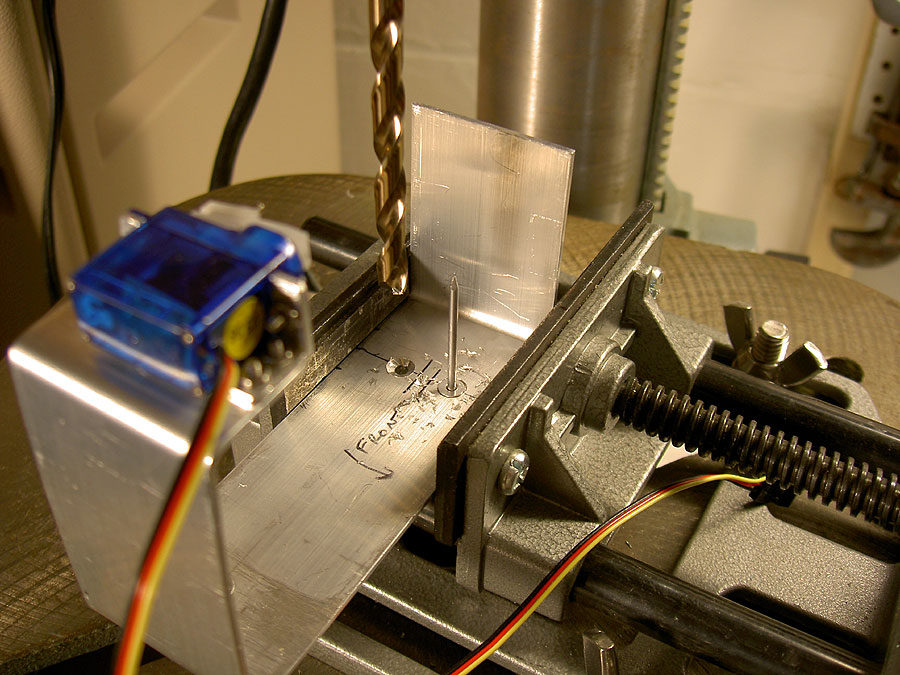
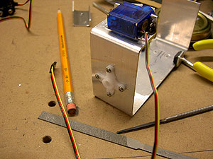
Tilt Servo Arms Fitted I didn't do a detailed series of photos of this step, but you must be getting the idea by now. I found the pivot point on the camera horizontally and vertically (hint: balace the camera on its bottom and back on a pencil) and used that to figure out where to put the center hole in the servo arm. That allowed me to find the position of the four small screw holes and they got drilled. During final assembly, a screw comes from the bracket into the servo. This crank arm, which came with the servo, is fluted to mate with the shaft of th servo. I don't have the matching hole on the other end of the camera tray yet for the other pivot point. Minolta G500 digital
|
So is that it? Just about. The other pivot point needs drilling and, once you see how low it is, it would be pretty easy to saw off some camera tray material to save a few grams, either that or drill some lightness holes in it. I haven't done either of these things yet. But you get the idea; this is fiddly work and you have to wade through it yourself. Depending on your mindset, this could be an annoying distraction or a lot of fun. I enjoy it, at least during the colder months.
by Matthew Cole, Saint Paul, Minnesota email me