KAP | Modifying a Hitec HS-85MG Servo to Continuous Rotation
A useful modification for any KAP rig is to change the pan servo to continuous rotation so you can pan the KAP rig through 360 degrees of arc smoothly. This modification is not strictly needed; you can use the roughly 70 degree or so movement of the unmodified servo, put a large gear on it, and have it engage with a small gear with one-fifth of the teeth. This will give you a full pan capability as well, but you might find it too fast-moving to offer good control. My first rig was continuous-rotation but direct drive which I found fast and twitchy; I can't imagine what a speeded-up pan mechanism would be like, but on the other hand, someone as accomplished as Cris Benton went years using this fast-pan method and did superb work.
When building your rig you will need to decide how to handle the panning. I decided to modify my pan servo to continuous rotation, use a metal-geared servo for durability, and to gear down the rotation so it wasn't even as twitchy as direct-drive. I happen to own Hi-Tec radio gear and like and understand their servos, so stuck with their stuff and chose a Hi-Tec HS-85MG (metal gear) servo for my digital rig. This wasn't exactly a radical new choice as this is precisely the servo I had already used on my Contax G1 rig.
The pictures and descriptions below will take you through the steps I performed to modify the servo and then to tap the output gear of the servo to a 4-40 thread. This continuous rotation thing, on this servo anyway, is very straightforward. (Note: as on most pages in my site, if you click on the photos below you will get a larger version which lets you see more detail.)
|
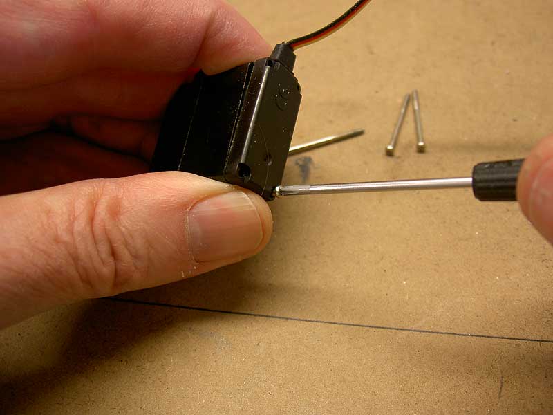
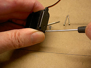
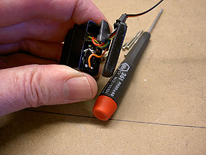
Take Apart the Servo The first thing you need to do to perform the Continuous Rotation modification is remove the front cover of the servo. The screws for this extend all the way through the servo, so you undo them from the back, as shown in this photo. Minolta G500 digital
|
 |
 |
| This is view of the back of the open servo |
And this is the view of the open front of the servo. |
|
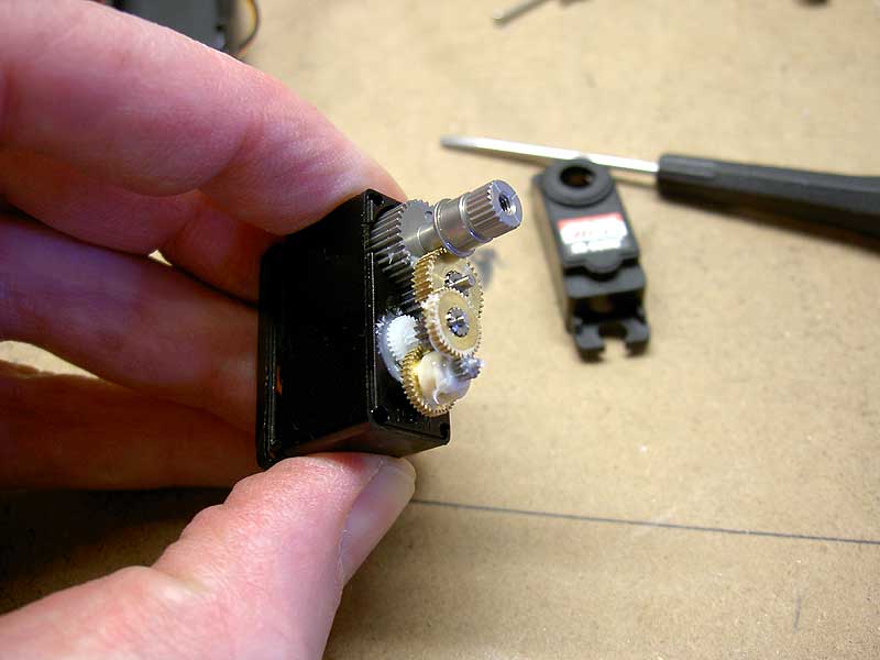
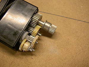
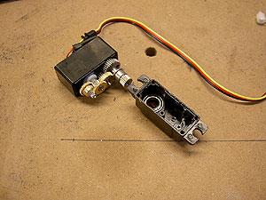
Note How it Goes Together You're about to disassemble this unit so you'd better pay attention to how it goes back together. Careful drawings can help, this digital photography thing works great or, if you are using the same servo as I am, you can just look at my photo! These are the output gears of the HS-85MG servo prior to disassembly. That white mess is the lubricant grease. Minolta G500 digital
|
|
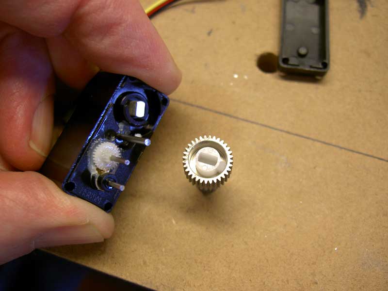
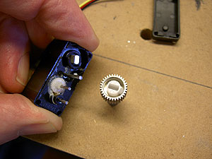
How the Servo Turns the Pot Frankly, my understanding of precisely how the RC stuff works is a bit vague. You move the stick on the transmitter and the servo rotates, changing the position of a potentiometer (pot), until something comes back into balance and then it stops. Something like that. These servos all turn their pots when they are activated. On the HS-85MG, the final output gear has a slot cut in it which mates to a tongue on the pot; the servo rotates, the pot gets turned, things come back into equilibrium and the pot stops turning. One way to make a servo continuous rotation it to disengage the pot from the output gear. That's what I am about to do. Minolta G500 digital
|
|
The Required Surgery The first time I did this I carefull Dremmelled off the stop tab on this plastic insert that limits movement, then tried to drill out the plastic insert so it was a round hole rather than a slot. Just as I was finishing this drilling, the whole plastic piece came loose! Oh No!! Then I realized that this piece was basically surplus to requirements and could simply be yanked out. That's what I did here. Give it a yank and Voila!, you have a continuous rotation servo.
Note that, before reassembly, you will want to plug the servo in and turn on the transmitter and get the pot positioned so that the servo doesn't rotate. Or you could do what I did; forget about it, reassemble everything, plug it in and find that you have a true continuous rotation servo since it will not stop! Yaaaah! Minolta G500 digital
|
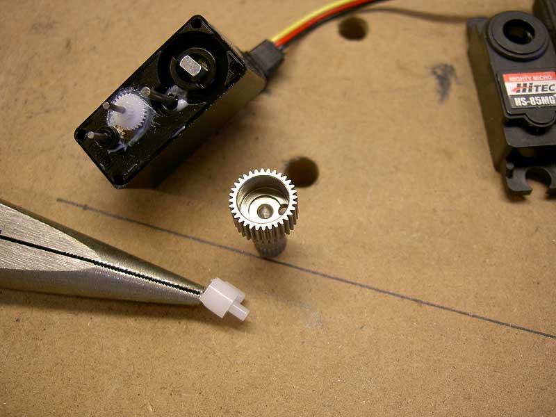
From the point of view of modifying the servo to Continuous Rotation, at this point you'd be done. This servo will rotate through 360 degrees with no problem. In my pan design, I want to mount a small gear on this output shaft. To do this, I need to thread the output gear to a 4-40 thread so I can attach a shoulder bolt (from Small Parts Inc.) on which will go the small gear. Since I have this servo apart already, I might as well thread the thing.

|
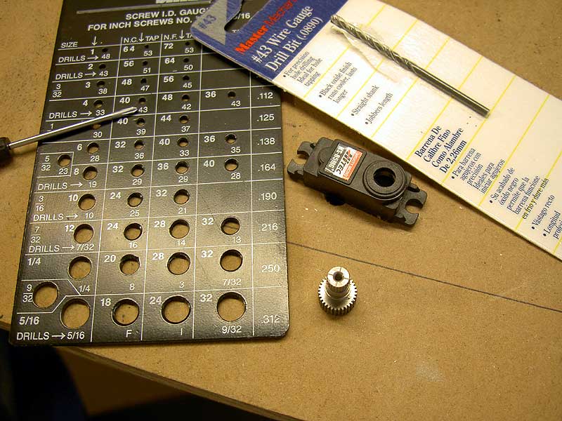
Preparing to Tap the Output Gear To thread this gear I am going to use a 4-40 tap. As you can see by where the screwdriver is artfully laid in the photo, this will require drilling a hole using a #43 drill bit. You aren't going to find this bit in your drill bit set from Target; it is one of a sequence of precisely-sized bits and I buy mine one at a time, as needed, from the hardware store. You can see the packaging for it lying in the photo. The black metal thing is useful for checking threads on fasteners you are unsure of and also has the clearance and tap bit sizes. I neglected to lay the tap down in this artistic tableau. Minolta G500 digital
|
|
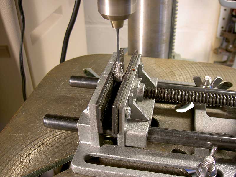
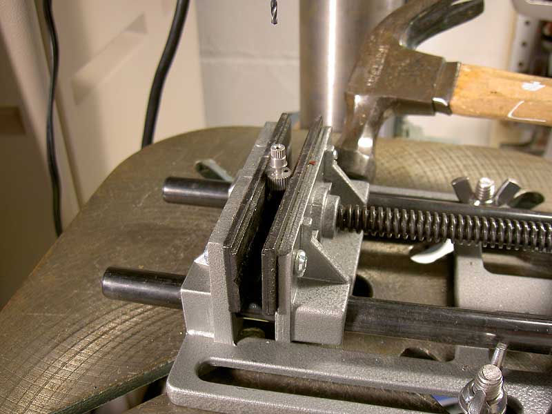
Carefully Position the Workpiece The hole to tap into needs to be precisely positioned. This isn't too hard with the drill press. Here the gear is clamped in the drill press vise, the drill press table has been locked, the vise lightly tightened down and I am moving the vise the last few, what, thousandths?, of an inch into place. The hammer, gently employed, helps greatly in making these final positioning moves. Note that my drill press, seen vaguely in the background here, is pretty burly. I owned this long before I tried KAP. If you don't own a drill press already, I'd recommend it, but if it's mostly for light work like this I'd buy a smaller, cheaper benchtop model. Minolta G500 digital
|
|
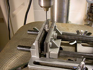
Drilling the Hole to tap out With the workpiece positioned and clamped into place, you can drill the hole. The drill press is set to its slowest speed (460 rpm in my case) for drilling metal. You can also set the depth so it will only drill to a certain depth, and I have done that here. In this photo the drilling is actually occurring. Minolta G500 digital
|
|
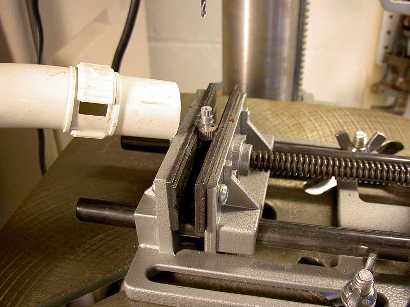
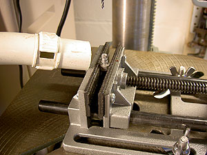
Cleaning Things Up It's a good idea to keep things tidy. Here I vaccuum up the mess while things are still clamped down. When working around small parts it's a good idea to be careful with the vacuum. While I have never sucked up, say, all the output gears for a servo or a bunch of 4-40 hardware, I did inadvertenly vacuum up a screwdriver which became lodged in the first bend of the vacuum pipe. I had to saw off several inches of vacuum hose to get it out, hence the stubby hose-end here. Be Clean but Be Careful. Minolta G500 digital
|

|
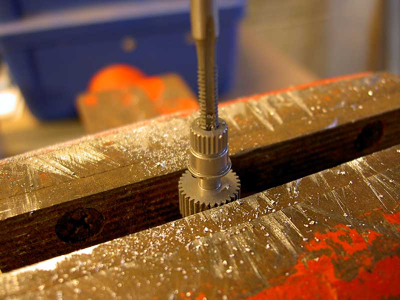
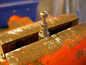
Tapping the Output Gear I clamped the output gear in the vise, mounted the tap in the tap handle, and tapped out the gear, cutting a set of 4-40 threads in the gear. There are threads in these output gears already, but good luck finding what they are. The local hobby shop thought they might be 2.6mm metric threads but apparently it's all very ill-documented. You probably aren't going to find these fasteners and hardware anywhere. The 4-40 thread, by contrast, is bigger and gives me some options. Minolta G500 digital
|
|
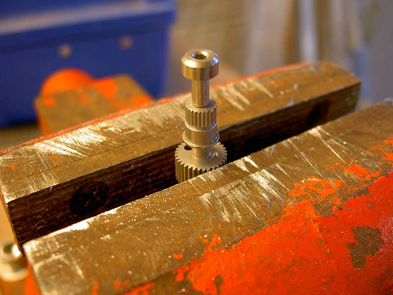
The Shoulder Bolt The option I went with was a 4-40 shoulder bolt from Small Parts, Inc. Early on, when I was first acquiring parts for the very first rig, the one I didn't actually complete, I ordered a bunch of interesting hardware from Small Parts Inc. Included in the order were these shoulder bolts. The shoulder happens to match well with some aluminum gears available from hobby stores and it is these that I have chosen for my pan mechanism. Minolta G500 digital
|

|
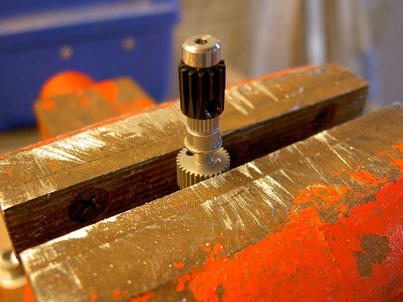
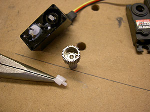
The Shoulder Bolt with Pan Gear Here the small pan gear is in place. It slides onto the shoulder and a small set screw tightens against the shaft and locks it in place. In my pan mechanishm, this small, continuously-rotating gear will "crawl" around a larger gear attached to the suspension bolt (and Picavet Cross) of the rig. Minolta G500 digital
|
|
Putting It Back Together Here I am reassembling the servo. You can see the inside of the front cover with the ball bearing insert in it. I like this on a servo that is going to be in constant use or which has to bear weight. On this digital rig, I used the same servo model for the tilt servo (although unmodified as to rotation--I got to 90 degrees using the trim settings on the transmitter). On the Contax G1 rig, where the camera is much heavier, I used a beefier HiTec HS-225MG with two bearings, metal gears and more torque. Minolta G500 digital
|
|
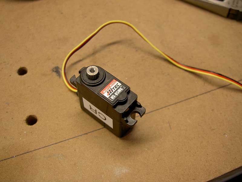
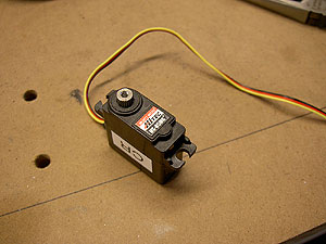
The Modified Servo All Done Here the servo is all reassembled and I have marked it with a "CR" for Continuous Rotation. The output shaft is threaded (although I have removed my shoulder bolt and gear) and ready for mounting on my pan structure, but that's a different project, one of many little time-consumers involved in building a KAP rig, and is covered in a separate page. Minolta G500 digital
|
I didn't time this procedure, but the Continuous Rotation modification is actually pretty quick. Once you figure out that all you have to do is rip out that plastic sleeve, this goes really fast. The threading of the gear takes some more time and involves the extra runs to the hardware store if you don't already own the drill bit, tap or tap handle.
by Matthew Cole, Saint Paul, Minnesota, USA