>
KAP | Making the Main Frame of the KAP Rig
by Matthew Cole
My rigs are of very conventional design and embody no real advanced design features. However, to someone unfamiliar with KAP rigs or working with aluminum, this page will provide some guidance on what is involved in building a rig.
My original KAP rig was built from one of Brooks Leffler's Brooxes Basic Radio Rig (BBRR) kits. I have said elsewhere how clever I think this design is, but one weakness of it is the way the tilt servo is connected by only two screws and is otherwise unsupported and unprotected. To me, this looked vulnerable to damage and, sure enough, eventually I whacked my rig hard enough to bust off the two screw eyes by which it was attached to the rig. Admittedly, this was in my basement and not in operation in the field, but it still highlighted the exposed nature of this tilt servo.
In my design, I wanted to protect the tilt servo and camera from damage as it seems to me the rig is susceptible to being banged into things, particularly the ground, when operating the whole thing solo. To this end, I made my main frame of the rig (perhaps the pan bracket would be another name) with extended sides to protect the camera and inserted the tilt servo through one side of this frame. The tilt servo is entirely surrounded by aluminum in this case, and attaches by the two mouting screws (the BBRR had four attachment points as it was a bigger servo than I used here). The only things is, to do this, I needed to put a rectangular hole in my main frame material.
I did this using a Klein nibbler. I like Klein tools, they make me feel like a pro when I use them. I'm not sure what the pros use the nibbler for, as it seems slow to cut, but it seemed the perfect tool for doing this rectangular cutting on this KAP rig. You can see below what I did with it while building this main frame piece.
|
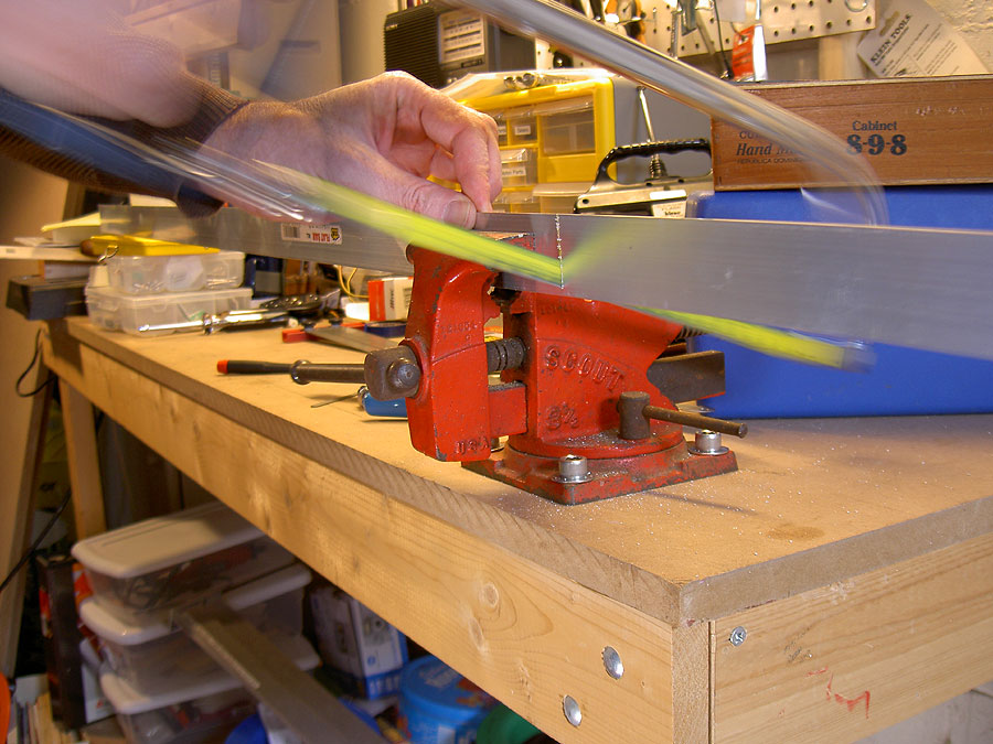
Cutting The Aluminum The first step is to cut out the aluminum for the main frame piece. This workpiece will then be bent (and I go on about bending metal in the Camera Bracket page) and will need some holes drilled in it. Here, using clever slow shutter speeds, I sut off a piece of aluminum from my 72" long 1.5" X .0625" metal strip.Minolta G500 digital
|

|
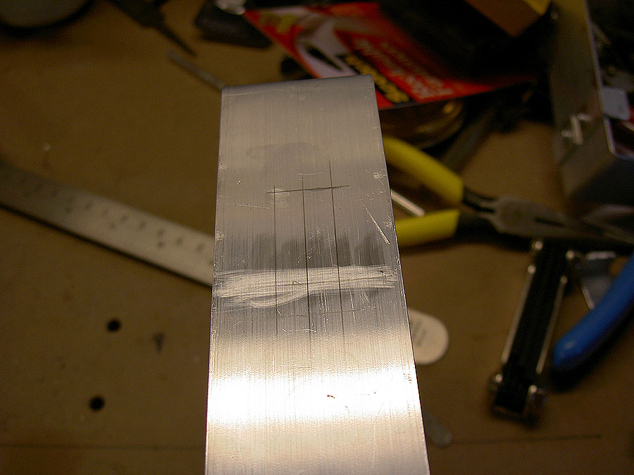
Marking the cutout I carefully measured the servo and marked the hole size and position on my workpiece. The servo is going to mount right through the main frame and I need to make a rectangular hole for the servo and then a couple of round holes for the mounting screws. I use a small precision marking square to mark off my cut.Minolta G500 digital
|

|
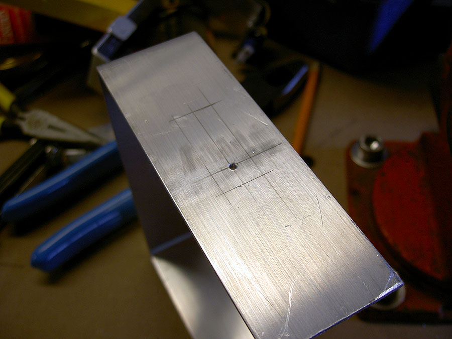
Drill a pilot hole first The Klein nibbler is going to need a 7/16" hole drilled for it to stick through before it begins cutting. From bitter experience I've learned that you probably don't want to just chuck up a 7/16" drill bit and bore a hole. A pilot hole, precisely located, will give the latger drill bit a guide and leave you with a neater, rounder hole. In this photo, I've drilled my pilot hole in the center of the area to be cut out. Minolta G500 digital
|

|
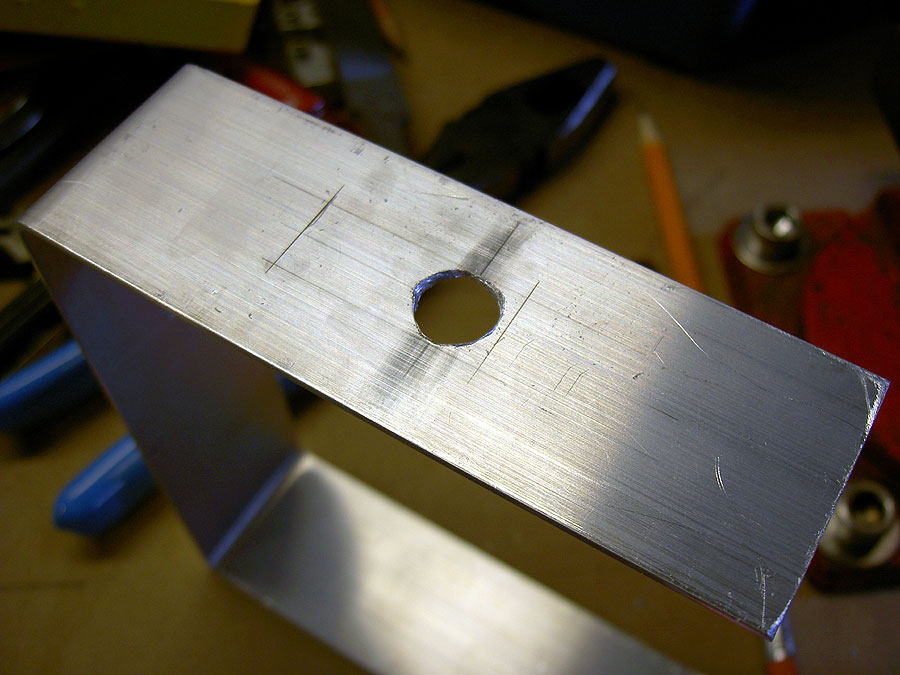
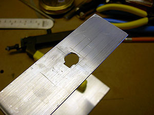
Drill the entry hole for the Nibbler The Klein nibbler requires a 7/16" entry hole. Having already done the pilot hole, I know drill out the full sized holes. While this is better than past efforts, the edges still aren't that clean. Oh well, bring on the Nibbler! Minolta G500 digital
|

|
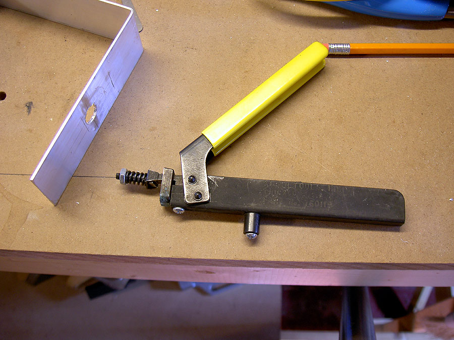
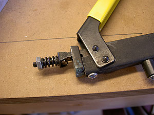
This is the Klein Nibbler This is what the tool looks like. Minolta G500 digital
|
|
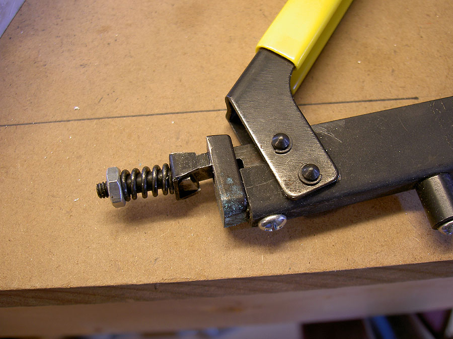
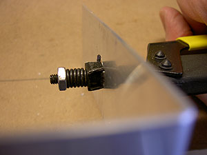
A close-up of the working end This is the working end of the tool. The piece with the nut and spring on it is going to stick through the hole we drilled. There's a lite cutter in there that's going to be drawn down through a hole in the supporting part of the tool, which I will call the anvil. Minolta G500 digital
|

|
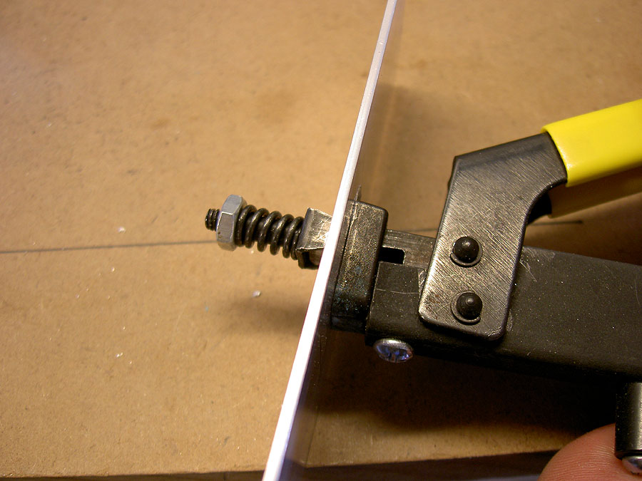
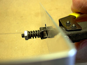
The Nibbler in position in the workpiece The Nibbler. Sounds a bit like a Batman villain! This is the Nibbler inserted into the workpiece and ready to nibble, er, cut. Minolta G500 digital
|
|
The Nibbler Guillotine before the cut The Nibbler is in place and the anvil is ready to cut. All we have to do is squeeze and..... Minolta G500 digital
|
|
The Nibbler Guillotine after the cut ...chop, out comes a small bite of alumninum. You have to do this over and over again, hence the name Nibbler and not, for instance, Chomper. Minolta G500 digital
|
You can, by the way, see an actual cheesy video of the Nibbler in action. I used the video record feature on the G500 to take this, the quality is not great and you get to hear a remarkably clear bit of sports talk radio, and the clip is 3.2 Meg so don't do it if you're in a hurry, but if none of that discourages you, try watching my Cheesy Video of Nibbling Aluminum.
|
What the first nibble looks like This is what the initial nibble out of the 7/16" hole looks like. What if your final hole is less than 7/16"? Well, time to get a bigger servo! Minolta G500 digital
|
|
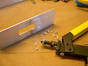
What the last nibble looks like At my level of skill, the Nibbler does not leave a finished edge. This is the workpiece once all the nibbling is finished. You can see a small collection of nibble wasted on the bench by the tool. Minolta G500 digital
|
|
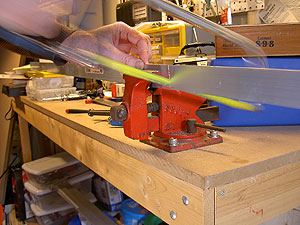
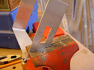
Time to clean up! One of the reasons to use aluminum is that it is so easy to work with. You nibble out close to the drawn outline, then clamp the workpiece in the vise and use a file to tidy up the edges and achieve a final fit. This would be lots harder with titanium. Might be OK with wood, but I've been an aluminum guy on my rigs. Minolta G500 digital
|
|
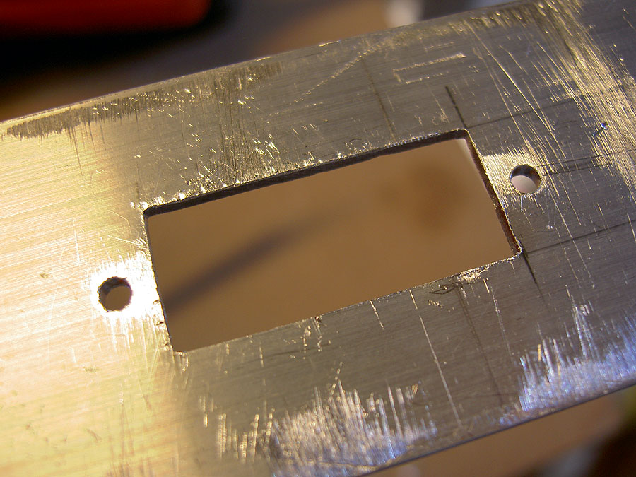
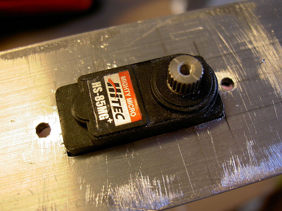
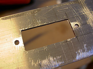
All Tidy By the time I took this photo, I'd cleaned up the tilt servo hole and also drilled the holes for the mounting bolts for the servo. This servo is smaller than the one on my first BBRR rig, so only has one mounting bolt on each end rather than two. With this design, the rotation forces on the servo are taken by the whole servo case, which will be tightly snuggled in this hole. Minolta G500 digital
|
|
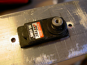
And it fits! Here is my servo fitted in place, though not yet attached. I am using the fairly strong HiTec HS-85MG (Metal Gear) servo for my tilting purposes. This seems like a sensible choice but I don't have enough hours on it to know it will be durable enough. Minolta G500 digital
|
So is that it? Nope. That was the most involved piece of work on the main frame of the G500 rig. Once the servo was fitted, it defined where the other pivot for the camera tray had to go. I also installed Velcro to attach the receiver, battery pack and antenna, then, once everything else was done, found the balance point with the camera mounted and used that to find the position for the bolt from which the whole rig is suspended. This involved some more precision drilling and also some rough drilling as I knocked in some small holes for plastic zip ties to go through to hold various wires in their places. Still, you get the idea; you cut your metal and then drill and nibble a bunch of holes in it, working towards a balanced rig when you are complete.
by Matthew Cole, Saint Paul, Minnesota e mail me