KAP | Building a Shutter Release Servo Bracket
Kite Aerial Photography isn't just about the chicks and the fame. Nope, before you go out flying in front of your adoring public you have to build your rig. A lot of this is fairly routine, tedious work. As I am doing elsewhere on this site, I have pretty thoroughly documented the construction of my third rig, designed to hold my relatively new Minolta Dimage G500 digital camera.
One decision you have to make when designing your rig is how you are going to fire the camera. On my first rig, one of Brooks Leffler's Brooxes Basic Radio Rig kits, the camera was fired by a short arm on a servo positioned to hit the shutter release. My second rig, and the first I built from scratch, I was using a Contax G1 camera which accomodates an electronic release. On that rig, I had a tiny servo push a momentary-on switch that electronically fired the camera. If you are adventurous and don't mind taking apart your nice new digital camera, you can buy an electronic switch called the Schiappi switch and wire it into your camera directly. In a year or two, when my brand new digital is worth about $25 in a bull market maybe I'll try it, but it is my first digital camera and I am loathe to take it apart just yet.
So, I decided to do the direct push-of-the-button method again, but using the tiny HiTec HS-55 servo, which weighs 8 grams. You can actually get a slightly lighter HiTec servo, the HS-50, but it only works at 4.8 volts and, while that is what I am using at the moment, I didn't want to constrain myself by having one servo with a voltage limitation compared to the others.
My rig design is still very simple, a double-U with the camera tray pivoting under the main (or pan) frame. I decided that rather than add arms and whatnot to hold the servo, I'd just carry the camera tray side up and over the camera and mount the shutter release servo there. I bent the tray to shape (using my Mighty Mite brake), cut it to length and then had to make a small bracket to hold the servo. That one tiny piece is what this page is about.
|
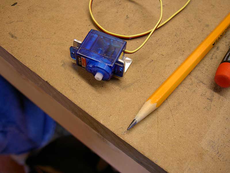
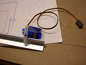
Estimating Amount of Material I decided to use the HiTec HS-55 Feather servo as my shutter release servo. This thing is going to have to be mounted on the camera bracket in such a position that it can push on the shutter release of the Minolta G500 digital camera. I am using 1/2" X 1/2" X 1/16" aluminum angle material to make the bracket and here have the servo next to it to estimate how much material to use. In the background you can see my "plan" for the rig, where I carefully traced (in red) the actual outline of the G500 then drew in the frame to go around it to estimate the material sizes I'd need.Minolta G500 digital
|

|
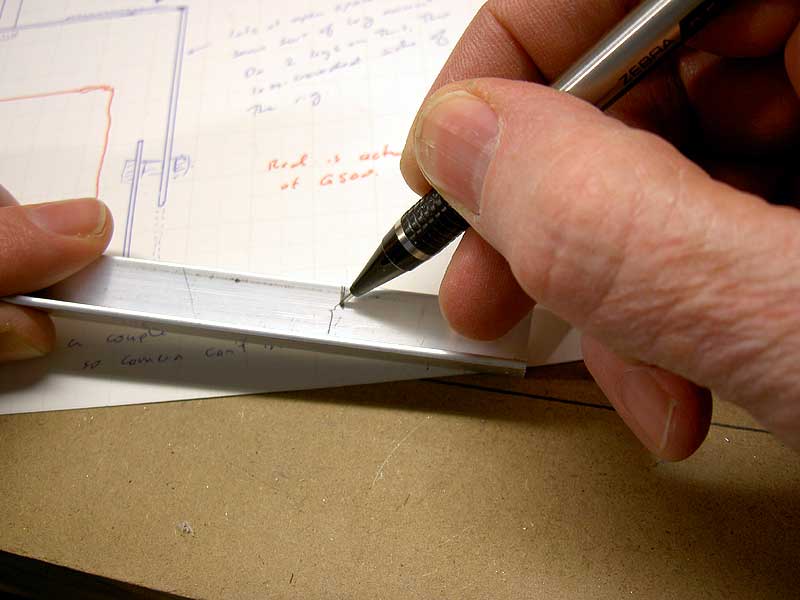
Marking the Material Here you can see my careful precision marking of the material. OK, my hand slipped while I was trying to take a picture. Still, I'm amazed when I go on factory tours how they can make thousands of parts with unerring precision while I can hardly cut two pieces of wood the same length.Minolta G500 digital
|
|
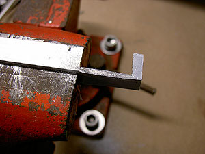
Cutting the Servo Hole This piece is going to be a small L-bracket with two tabs sticking up to bolt the servo to. I need to remove the material for the width of the servo, so did some of my careful precision marking, cut the outside ends of the gap out with my small hacksaw then flexed the tab out of the space. This is right after having done this. Aluminum is handy this way--it can be flexed back and forth and will break off. The bottom of this gap shows the signs of this stress still, while the beginning of a slot shows where I will cut this to length. I figured that it would be easier to remove this big piece before I cut the bracket to length, leaving me more to clamp in the vice. Minolta G500 digital
|
|
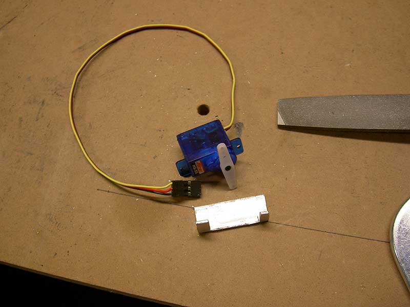
The Workpiece cut down to size At this point I have the raw workpiece. My bracket has been cut to length off the long piece of aluminum and I have removed the material for the servo to fit in. I haven't tidied --some of those rough edges and sharp corners need to be smoothed out. Minolta G500 digital
|
|
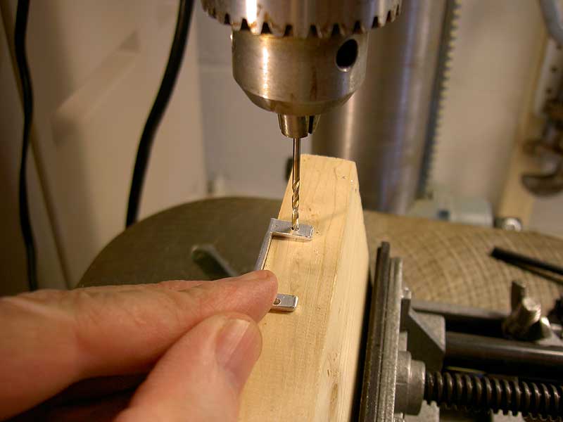
Drilling Holes to Mount Servo A lot of rig construction involves putting small holes in the right places. Here I am drilling the holes to mount the servo. These are going into the tabs on the workpiece and these are a bit fragile, so I have the whole thing supported on a piece of wood clamped in my drill press vise. The HiTec HS-55 doesn't need burly bolts to hold it in place; I will use a pair of 1-72 bolts (bolts seems to manly a word for these small fasteners). Officially, these want a #48 drill bit for a clearance hole, but I didn't have one, so used a 5/64" bit from my regular drill bit set. Minolta G500 digital
|

|
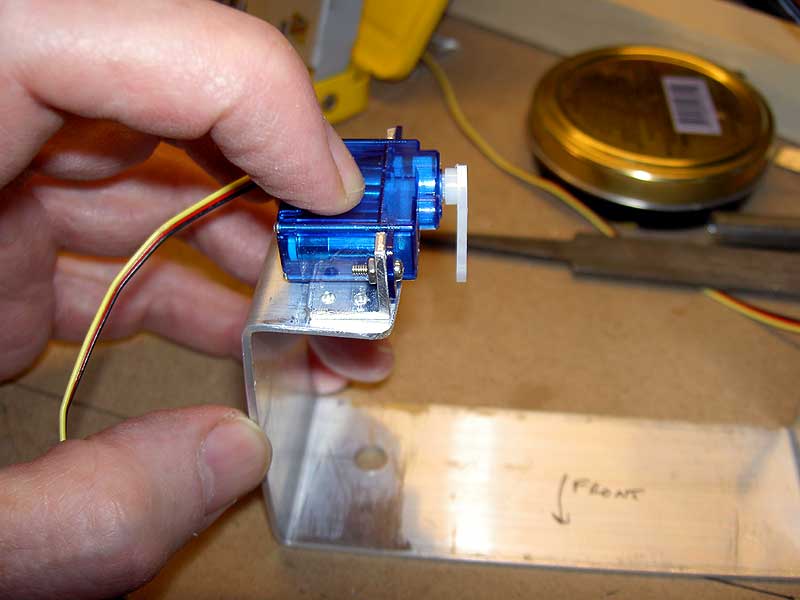
Fitting the Servo to the Bracket Here I am checking the fit of the servo to the bracket. It has to fit snugly in the opening and be correctly lined up with the bolt holes I've just drilled. It is not always the case that my pieces fit all that well. In my experience, it is best to cut openings like the servo opening slightly small and file them out to size. The holes, those you pretty much have to get in the right spot. This all seems to be fitting pretty well. Minolta G500 digital
|
|
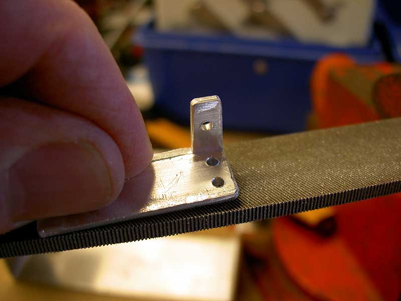
Tidying Up the Workpiece I needed three holes to attach the bracket to the camera tray. In this photo you can see that I've drilled these into the lower tab of the bracket. I have two on one side and one on the other. You get these little messes on the side where the drill bit comes out, and here I'm filing these down float. I've also tidied up the corners a bit, softening them just a little. This is one of those occasions where I've found it useful to clamp the file in the vise and move the workpiece back and forth. Minolta G500 digital
|
|
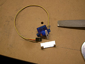
Positioning the Bracket They build 777s by doing careful drawings and subcontractors around the world built components which all come together and fit precisely. In building the rig, I don't try and predict where exactly this part goes; I hand-position it. Since I am using the camera to take these photos, you don't see it, but I mounted the camera in the camera tray and figured out where to put the bracket so the arm on the servo would press the shutter release button. Here it is possible to see why I'm making this bracket. If I was really clever, I might have bent the frame piece up at this end and cut out the servo hole from that, but I'm not that good. Minolta G500 digital
|
|
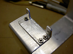
The Bracket in Place Here the bracket has been attached to the camera tray. Three points define a plane, so I have three of the massive 1-72 bolts holding this in place. You have to assemble this bit first, before attaching the servo, because the bolts for the servo blocks access to these mounting bolts on one side when the servo is in place. Minolta G500 digital
|
|
|
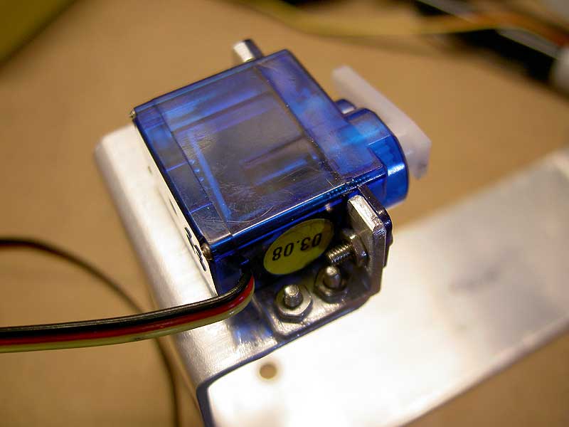
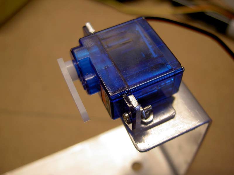
The Servo in Place Now the bracket is in place and the servo has been attached. This shows two views of this. The arm on the servo would turn out to be a hair short, so in other photos on the site you may see how I extended this arm just a little.Minolta G500 digital
|
There. I didn't time this, but it was probably an hour altogether, maybe a bit longer. All to get one piece. Rig construction can take a remarkable amount of time, especially the first time through. At least here in the Twin Cities the winter makes for a natural rig-building season, dark nights and cold days in the basement, working with the rig and dreaming of nice balmy May days with the kite out flying. Ahhhh.....
by Matthew Cole, Saint Paul, Minnesota e mail me